40 Years of Performance
Hutton TLP Case Study and the Impact of Highly Loaded
Lamellar Glass Flake in Offshore Coating
40 Years of Performance
Hutton TLP Case Study and the Impact
of Highly Loaded Lamellar Glass Flake
in Offshore Coating
40 Years of Performance
Hutton TLP Case Study
and the Impact
of Highly Loaded Lamellar
Glass Flake
in Offshore Coating
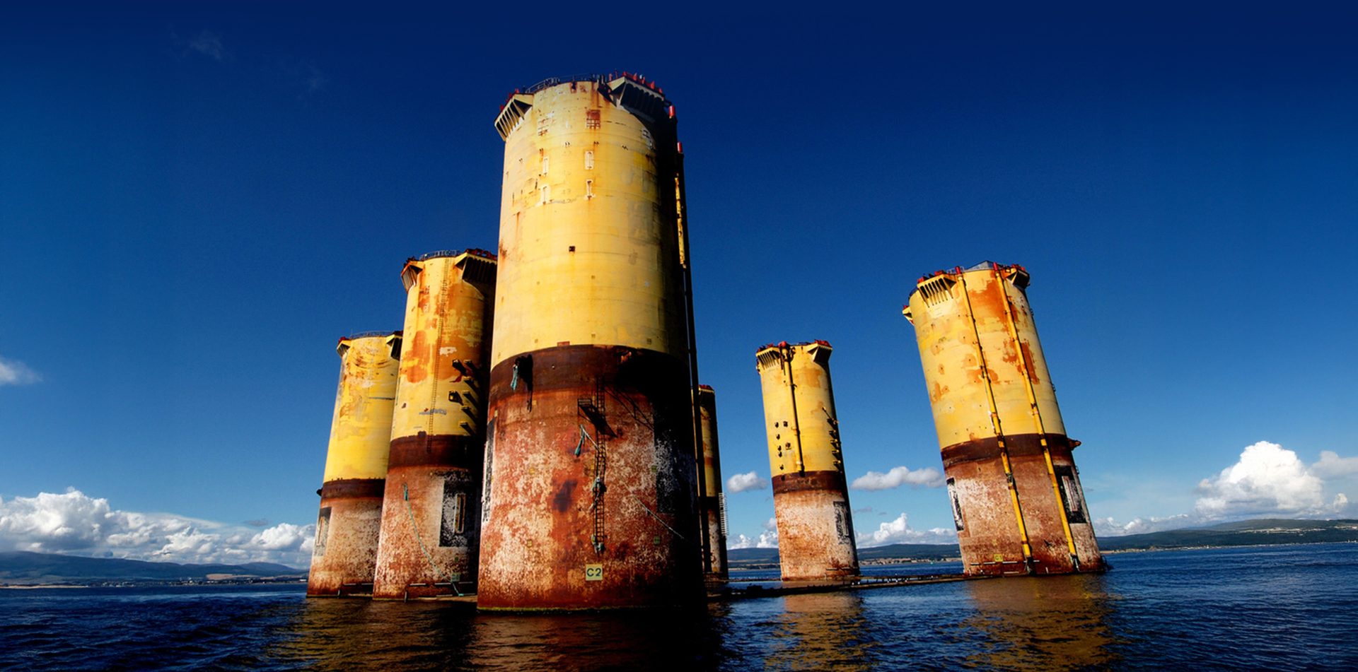
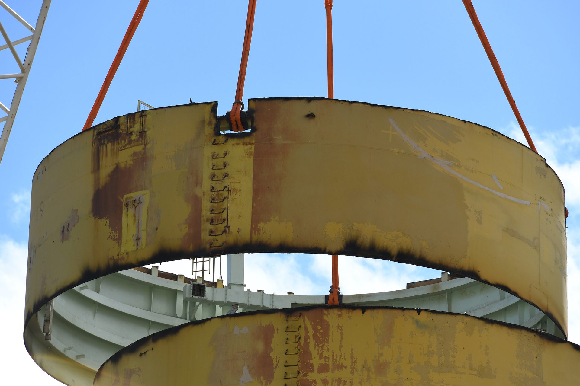
–Credit: Courtesy of Nerida Decommissioning–
By AkzoNobel
In the offshore environment, both for the oil and gas (O&G) and wind energy sectors, there is an increasing need to extend the lifetime of assets to 40 years or more. The main drivers of this change are to reduce the need for expensive and hazardous maintenance in difficult-to-reach offshore locations and to minimize the environmental impact these assets have over their lifetime.
Currently, there are no recognized industry standards for accelerated testing beyond 30 years. This leaves paint manufacturers with the critical question: “How do we prove our coatings can last beyond 40 years?” Our approach to answering this question involves examining long-standing real-world examples of assets and utilizing both existing and new testing methods to determine the expected durability of our coatings.
Two recognized accelerated testing approaches used in the industry to determine the lifetime expectation of a coating system for splash zone and immersed areas are water immersion and corrosion creep at the scribe.
Water Immersion
Long-term water immersion tests and cathodic disbondment tests form part of recognized standards such as ISO 12944 and NORSOK M-501. Newer standards, such as ISO 24656:2022, provide guidance for long-term durable coating systems for both immersed and partly immersed areas offshore and recommend the use of epoxy coatings with highly loaded lamellar glass flake (> 20%) for the longest durability (Figure 1 and Table 1).
FIGURE 1–ǀ–Illustration of water permeability.
X

REVERSE PINCH TO ZOOM
X

REVERSE PINCH TO ZOOM
X
REVERSE PINCH TO ZOOM
X
REVERSE PINCH TO ZOOM
Credit: Courtesy of AkzoNobel.
TABLE 1–ǀ–Extract from ISO 24656.
X

REVERSE PINCH TO ZOOM
X
REVERSE PINCH TO ZOOM
X
REVERSE PINCH TO ZOOM
X
REVERSE PINCH TO ZOOM
Notes:
- Some of the codes and standards referenced in Table 1 allow the use of zinc-rich primers. In this standard, zinc-rich primers are not recommended for use in the immersed, tidal and splash zones.
- The use of any of the coating systems in Table 1 demands that all coatings, surface preparation, application, inspection and testing have been carried out in full accordance with all relevant parts of the referenced related codes and standards.
Credit: Courtesy of AkzoNobel.
Corrosion Creep at the Scribe
Accelerated corrosion tests such as ISO 12944 and NORSOK M-501 utilize corrosion creep at the scribe along with set pre-qualification criteria. These methods measure the performance once the coating has been artificially damaged, and once the steel is exposed it will start to corrode, and the coating’s role is to slow down the expansion and spread of the corrosion due to underfilm corrosion (Figure 2).
FIGURE 2–ǀ–Typical scribe testing.
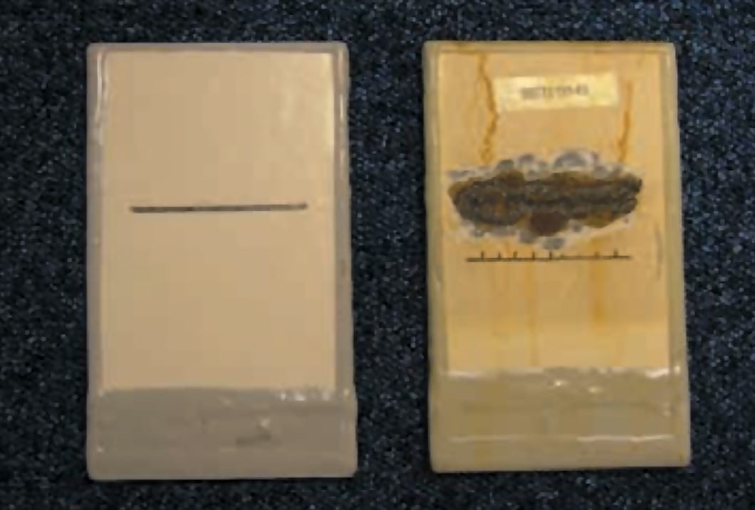
Credit: Courtesy of AkzoNobel.
The main function of a coating in the splash zone or immersed area is to ensure appropriate barrier protection and to prevent the external environment from causing steel metal loss. One way to achieve this is to ensure that the coating remains intact for as long as possible, thereby ensuring and prolonging low permeability and high barrier properties.
In this paper, we explore the durability of Interzone® 1000 when varying the loadings of lamellar glass flake. The loading of lamellar glass flake was varied, then subjected to a range of performance tests to ascertain a comparison versus the standard commercially available product. The paper also includes a review of how a commercially available product performed in an offshore real-world environment via a 40-year case study, evaluating visual appearance, adhesion, cross-sectional optical microscopy and electrical impedance spectroscopy (EIS).
Glass Flake Content Study, Part 1
Interzone 1000 is one of the longest-serving products within the International® range of protective coatings. It is designed for the most aggressive offshore environments, such as underdeck areas, splash and tidal zones, and subsea areas. Interzone 1000 offers an excellent combination of corrosion protection and resistance to mechanical damage in both atmospheric and immersed environments. It boasts an extensive track record, including 40-year performance testimonials, which is unmatched in the industry.
In these aggressive environments, Interzone 1000 typically utilizes high dry film thickness (DFT) combined with a high loading of glass flake. Interzone 1000 contains > 30% corrosion- and chemically resistant lamellar structure glass flake in the cured film. This glass flake significantly contributes to the high barrier against moisture ingress and reinforces the dry film, providing excellent resistance to mechanical damage such as impact and abrasion.
Furthermore, the ISO 24656:2022 standard (Cathodic Protection of Offshore Wind Structures) recommends a high-build glass-flake epoxy or polyester material containing at least 20% nonmicronized glass flake for the longest service life. This recommendation has led to questions about the glass flake loading level in Interzone 1000, with some competitors claiming that the > 30% lamellar structure glass flake level is excessive.
The aim of Part 1 of this study is to investigate the impact and abrasion resistance of Interzone 1000 when compared to variants with reduced levels of lamellar structure glass flake. The data from this work will show whether this reduction significantly affects the impact and abrasion resistance.
ADVERTISEMENT

Test Program
Variants of Interzone 1000 were formulated with glass flake levels varying from 20% down to 0% in the dry film. These were tested alongside the control formulation, Interzone 1000, with its > 30% loading level in the dry film. This resulted in the following four variants being tested:
- Interzone 1000 (standard product with glass flake loading at > 30%)
- Interzone 1000 (reduced glass flake loading to 20%)
- Interzone 1000 (reduced glass flake loading to 10%)
- Interzone 1000 (no glass flake loading – 0%)
There are numerous methods for assessing the abrasion resistance of a coating system. The most extensively used is the Taber abrasion test. However, there are concerns that this test does not provide an accurate gauge of a coating’s abrasion resistance.
In Part 1 of this study, the focus has been to evaluate performance in the following tests:
- Shear box (BS 1377 Part 7: Method 5)
- Gardner impact (ASTM D2794)
In addition, the mechanical properties, such as tensile strength and elongation, were investigated for the formulation variants to ascertain whether this data correlated with the abrasion resistance. The cyclic aging test (ISO 12944-9) was also included in the test program to understand whether the reduction in glass flake has a detrimental effect on corrosion at a scribe. Results from this study will be released in future parts.
Test Results
Shear Box - BS 1377 Part 7: Method 5
Abrasive cargoes such as bauxite, iron ore and coal are placed in a shear box, which is then positioned onto a coated steel panel with a set pressure ranging from 300 kPa to 1,200 kPa. The panel is dragged under the cargo at a set rate (up to 1.1 mm/min) while the pressure is applied (Figure 3). The coating loss or damage is then measured and categorized as either cohesive damage (damage within the coating) or damage down to the steel substrate (where the underlying steel is exposed to atmospheric conditions).
This test has been shown to differentiate coatings in a manner similar to in-service conditions and has been used for cargo settling and icebreaker coating assessments. It was originally derived from civil engineering purposes for the classification of soils and clays (BS 1377 Part 7: Method 5).
FIGURE 3–ǀ–Illustration of shear box test.
X

REVERSE PINCH TO ZOOM
X
REVERSE PINCH TO ZOOM
X
REVERSE PINCH TO ZOOM
X
REVERSE PINCH TO ZOOM
Credit: Courtesy of AkzoNobel.
Since Interzone 1000 sustains minimal damage, particularly down to the underlying steel substrate (which could lead to corrosion), the test parameters were slightly modified to investigate the coating’s endurance and to differentiate the various loading levels of lamellar glass flake:
- The cargo chosen was iron ore, the most aggressive cargo available for this test method.
- The pressures were significantly increased from 300 kPa to 900 kPa and to a maximum of 1,200 kPa.
- In addition to the standard scheme thickness (2 × 500 µm DFT), a single scheme thickness was investigated.
- Repeats of the test were carried out on panels to determine whether a second run would significantly impact the abrasion resistance, given the likely DFT loss from the first run.
The typical scheme thickness for Interzone 1000 is 1,000 µm (two coats at 500 µm per coat). Reducing the scheme thickness to 1 × 500 µm increases the likelihood of abrasion damage reaching the underlying steel substrate, thus being able to better visually correlate performance across the glass flake loading levels.
Duplicate panels were prepared as a single-coat scheme (1 × 500 µm DFT). Half of these panels were tested using iron ore at 900 kPa, and the remaining panels were tested at 1,200 kPa before being assessed for abrasion damage. Graph 1 shows how the coatings performed at the two different pressures.
The most critical performance parameter is the damage down to the steel substrate, as this could lead to corrosion of the structure. The damage down to steel was plotted against the glass flake loading.
The test at 900 kPa shows a significant difference between the highest and lowest loading levels of glass flake; the damage down to the steel substrate ranges from 0% to almost 1% when the glass flake is removed in the standard Interzone 1000 formulation. The damage to the 10% and 20% glass flake loading level is so low that there is no significant difference between these coatings.
The test carried out at an increased pressure of 1,200 kPa shows a much more obvious trend in terms of abrasion resistance and glass flake loading level. In this instance, the only coating with no damage down to the steel substrate is the standard Interzone 1000 with > 30% lamellar glass flake. The level of damage increases as the level of glass flake loading decreases.
GRAPH 1–ǀ–Comparative results from shear box testing.
X

REVERSE PINCH TO ZOOM
X
REVERSE PINCH TO ZOOM
X
REVERSE PINCH TO ZOOM
X
REVERSE PINCH TO ZOOM
Credit: Courtesy of AkzoNobel.
Gardner Impact (ASTM D2794)
The Gardner impact test assesses the resistance of a coating to rapid deformation following the impact of a specified falling weight from a specified height. This test method uses a metal cylindrical weight with a hemispherical indenter housed within a vertical tube. The tube, graduated in centimeters, guides the indenter as it falls due to gravity toward the test panels. The height (h) from which the weight is released is directly proportional to the impact energy, calculated using the equation:
E = mgh, where m is the weight of the drop tup and g is the gravitational acceleration.
The aim of Gardner testing is to find a drop height at which 50% of the tested specimens will crack. This height can then be converted to the impact energy that causes the coating to break down. Several impacts need to be performed to identify the impact damage energy. The result of the impact testing is shown in Table 2. The table provides the highest energy each coating variant can withstand and to what degree of success.

Suradech14 / iStock / Getty Images Plus via Getty Images


Buyers’ Guide Premium Sponsorships
Below are the premium listings from our PCI Buyers' Guide. For a complete list of companies and products, click here.
**CLICK HERE to see all product
photos, downloads, and more!**
For more than 100 years, Atlas has been a leader in materials testing, offering a complete line of weathering testing instrumentation, laboratory, and outdoor testing services.
**Product Categories**
Accelerated Weathering
Consulting, Technical Consulting
General Laboratory Equipment
Humidity/Condensation Chambers
Outdoor-Exposure Test Equipment
Testing Instruments, Misc. Testing Instruments
Testing Services/Laboratories
Weathering Chambers
TABLE 2–ǀ–Comparative results from Gardner impact testing.
X

REVERSE PINCH TO ZOOM
X
REVERSE PINCH TO ZOOM
X
REVERSE PINCH TO ZOOM
X
REVERSE PINCH TO ZOOM
Credit: Courtesy of AkzoNobel.
According to the Gardner test results, the impact resistance of the coating decreases in line with the decrease in glass flake content.
Findings
Within the scope of the testing carried out, the results from the shear box and Gardner impact testing indicate a reasonable correlation between the loading of lamellar glass flake content and the abrasion and impact resistance of the coating. This, in turn, within the scope of the testing carried out, demonstrates that a > 30% lamellar glass flake content, combined with the epoxy technology used in Interzone 1000, provides the most robust performance.
Hutton TLP 40-Year Case Study
In the previous section, we have given some evidence as to why Interzone 1000 would perform well over extended periods of time. Now we will show what that looks like in a real-world example.
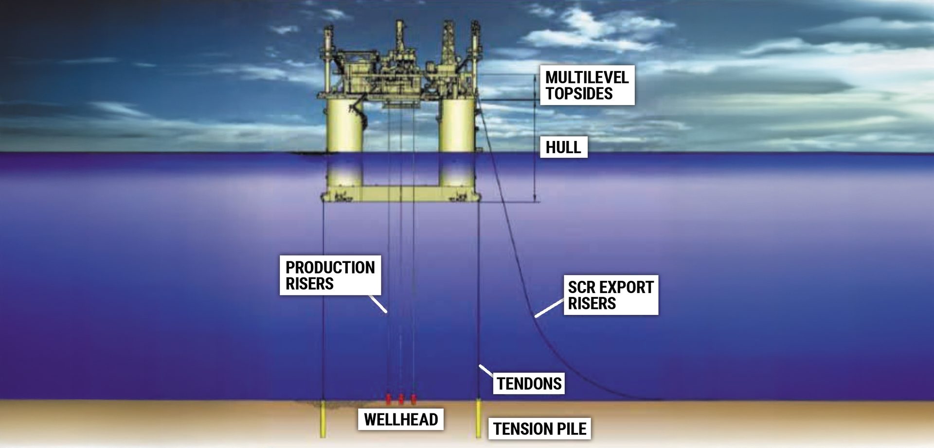
From 1982, a new design for offshore oil and gas production using a tension leg platform (TLP)³ was being used, allowing for exploration in deeper waters. A TLP is a vertically moored floating structure normally used offshore in the production of oil or gas and is particularly suited for water depths greater than 300 meters (about 1,000 ft) and less than 1,500 meters (about 4,900 ft) (Figure 4).
The platform is permanently moored by means of tethers or tendons grouped at each of the structure’s corners, where a group of tethers is called a tension leg. A feature of the design of the tethers is that they have relatively high axial stiffness (low elasticity), such that virtually all vertical motion of the platform is eliminated. This allows the platform to have the production wellheads on deck (connected directly to the subsea wells by rigid risers), instead of on the seafloor. This allows a simpler well completion and gives better control over the production from the oil or gas reservoir, and easier access for downhole intervention operations.
FIGURE 4–ǀ–Typical design of a tension leg platform.
Credit: Courtesy of AkzoNobel.
TLPs have been in use since the early 1980s, with the first tension leg platform built for ConocoPhillips for the Hutton field in the North Sea. The hull was built in dry dock by Highland Fabricators in Scotland, with the deck section built nearby at McDermott’s yard at Ardersier. The two parts were then combined in the Moray Firth in 1984.
The Hutton TLP was originally designed for a service life of 25 years in the North Sea, and at the time of construction, ConocoPhillips coating engineers decided to use a coating that was loaded with high levels of lamellar glass flake to maximize service life. The coating system selected for the jacket included a blast-holding primer followed by three coats of a high-build epoxy pigmented > 30% by weight of lamellar glass flake in the dry film, followed by an epoxy finish.
Specification:
- Abrasive blast clean to SSPC-SP 10 near-white metal with sharp angular profile of 75–100 µm (3–4 mils)
- Epoxy blast primer 25 µm (1 mil)
- Interzone 1000 500 µm (20 mils)
- Interzone 1000 500 µm (20 mils)
- Interzone 1000 500 µm (20 mils)
- Epoxy finish 75 µm (3 mils)
Production on the Hutton field began in August 1984,⁴ and the field was retired in the summer of 2001. During its lifetime, the Hutton TLP was exposed to 25-meter waves and 100 mile-per-hour winds. After this period, the Hutton TLP had a nomadic life as the platform was removed for re-use outside the UK. In early 2009, the hull section of the former Hutton TLP was relocated to the Cromarty Firth, Scotland, where it remained on station (Figure 5).
FIGURE 5–ǀ–Hutton TLP jacket on route to Cromarty.
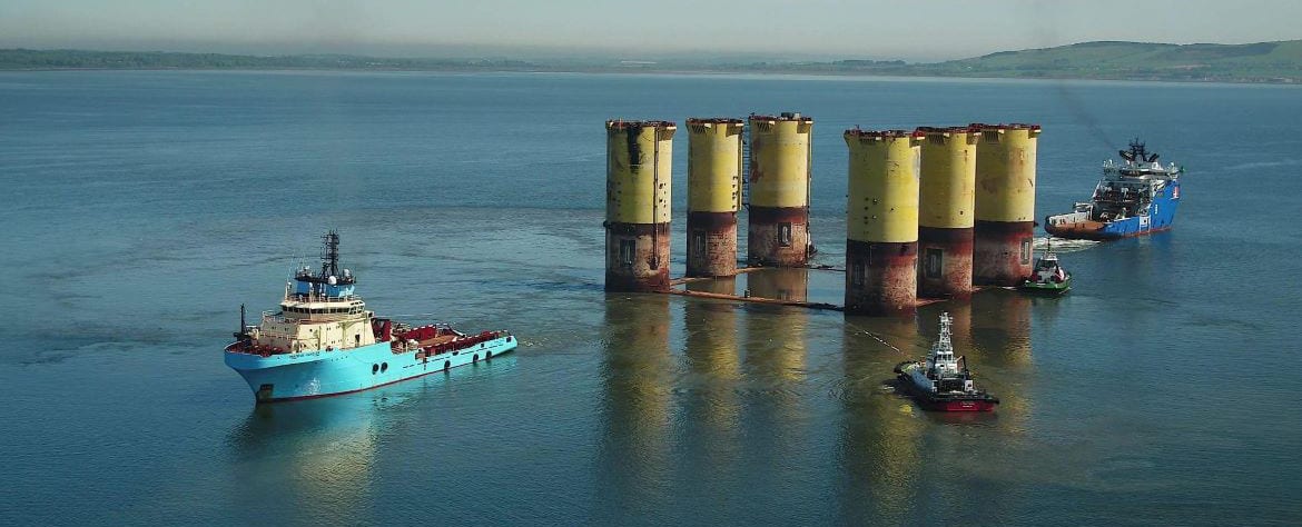
Credit: Courtesy of AkzoNobel.
In 2011, a visual inspection was carried out on the condition of the coating system and reported⁵ to be in excellent condition. After nearly 30 years in service, the highly loaded glass flake epoxy is still performing very well on the painted tubular splash zone sections of the Hutton TLP hull, with an estimated corrosion of less than 1% over the coated immersed and splash/tidal zone. The jackets remained at Cromarty until 2022, when the asset was subsequently purchased for decommissioning at Invergordon, thus effectively completing its life cycle close to the place where it was constructed.
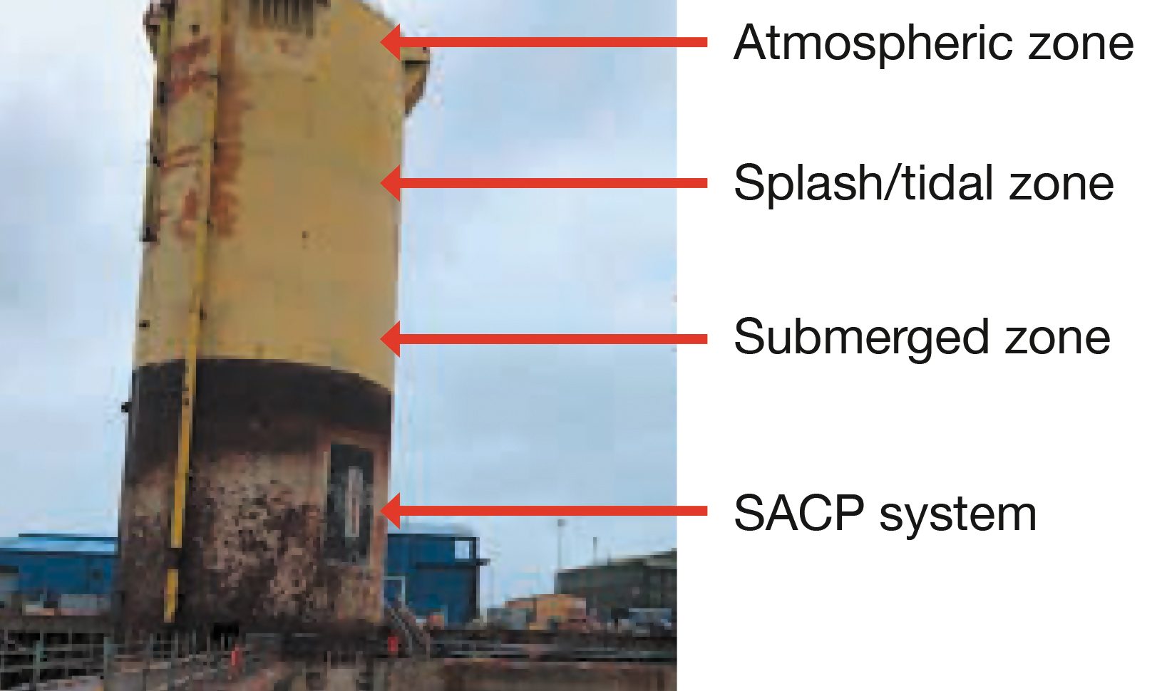
The Hutton TLP jacket has three separate environmental zones, including atmospheric and splash/tidal zones being protected by the coating system, and the submerged zone, which was protected using a combination of coating and sacrificial anode cathodic protection (SACP). Interestingly, the submerged zone only had the full coating system applied to approximately 10 meters below the waterline (Figure 6).
FIGURE 6–ǀ–Environmental zones on the Hutton TLP jacket.
Credit: Courtesy of Nerida Decommissioning.
Experimental Procedure
In early 2022, we were approached by Nerida Limited, who were responsible for the final decommissioning of the Hutton TLP jackets, with regard to the coatings applied (Figure 7). During conversations with Nerida Limited, it was agreed to provide test plates from the Hutton jacket for detailed inspection as to the condition of the coating system.
A coating inspection company was tasked with providing independent witnessing of the inspection of the coating system and provided a report⁶ on the results, which are discussed in detail below.
FIGURE 7–ǀ–Decommissioning process.
Credit: Courtesy of Nerida Decommissioning.
Visual Appearance
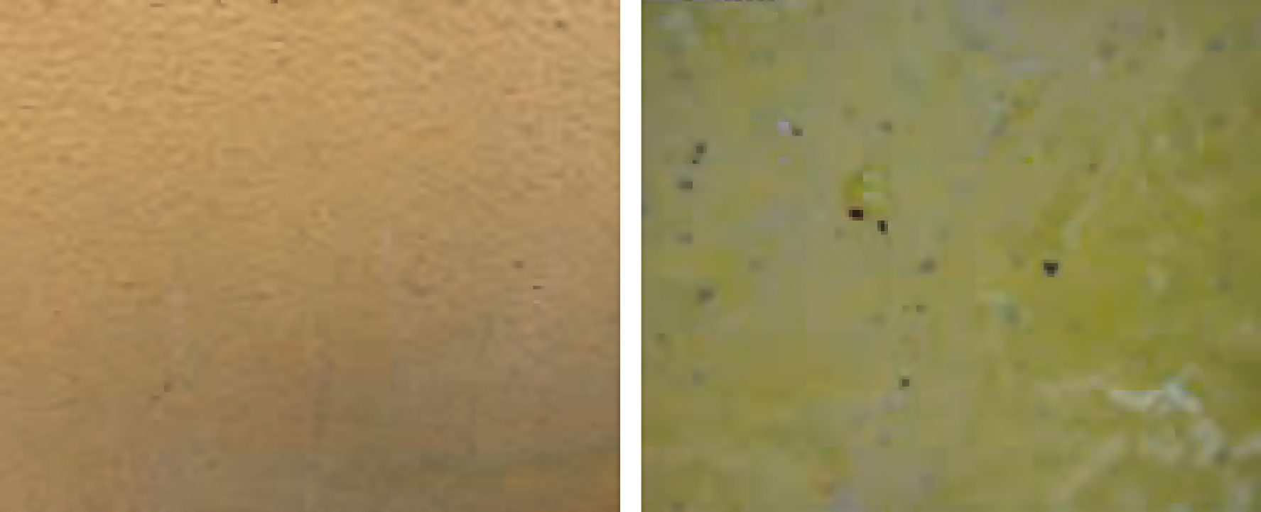
The general coating system appeared to be in excellent condition, with no visible signs of cracking, flaking, blistering or corrosion, even under 30× magnification (Figure 8).
FIGURE 8–ǀ–General appearance of the coating.
Credit: Courtesy of AkzoNobel.
Optical Microscopy
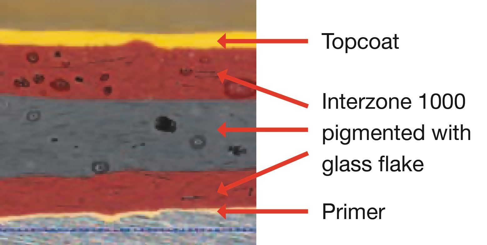
The steel plate was cut to expose the coating system and reveal the cross section, which was examined using digital microscopy at 300× magnification to look at the number of coats and typical thickness of each layer. From the cross section, the coating system consists of five distinct layers:
- A buff primer layer typically 25 µm (1 mil) in thickness, which is epoxy polyamide-based and pigmented with inert pigments.
- Layers 2–4 consist of Interzone 1000, typically ranging from 300–600 µm per coat (12–24 mils) in thickness. Each layer is pigmented with high amounts of lamellar glass flake, as can be seen below in Figure 9 as thin, plate-like particles well aligned throughout the coating.
- The top layer consists of a yellow topcoat of typically 75 µm (3 mils) thickness, based on an epoxy polyamide finish coat.
FIGURE 9–ǀ–Cross section of the coating system.
Credit: Courtesy of AkzoNobel.
The total dry film thickness measured on test plates ranged between 1,200–1,400 µm (48–56 mils), consisting of the holding primer followed by three layers of Interzone 1000 and finally an epoxy finish coat.
The epoxy topcoat on the sample plates generally appeared in good condition (Figure 10). However, on closer observation, some areas of the jackets had indeed suffered from signs of chalking and even complete removal of the topcoat due to long-term exposure to the damaging effects of UV irradiation. Some areas were more affected than others. This can be explained by the protection initially given to the jackets by the topside while in service. Once the topside was removed, some areas were generally more shaded than others depending on their position in relation to the sun. As expected, areas subjected to higher levels of UV will have chalked and eroded more, exposing the glass flake epoxy undercoat. In general terms, the epoxy topcoat has performed well.
FIGURE 10–ǀ–Condition of topcoat.
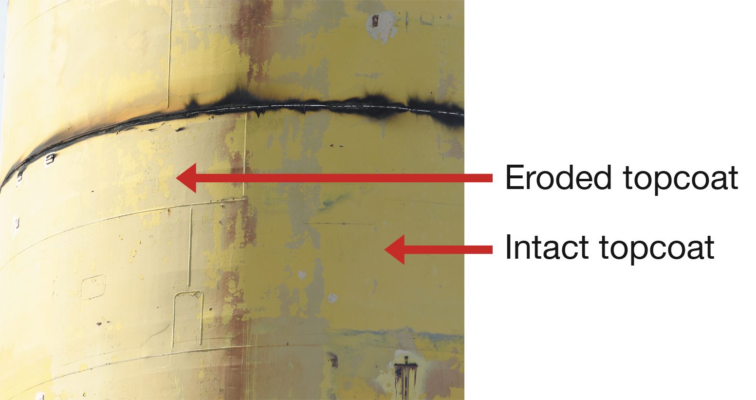
Credit: Courtesy of Nerida Decommissioning.
Adhesion Testing
Adhesion testing was carried out in accordance with ISO 4624⁷ using a self-aligned pneumatic adhesion tester. A total of six dollies were fixed to the coating system using two separate test plates. The adhesion values were high, with averages of 11.68 MPa (1,694 psi) and 13.69 MPa (1,986 psi), respectively, with failures typically occurring cohesively within the glass flake epoxy layer and no adhesive failures to steel, confirming the excellent performance of the coating system even after 40 years of exposure (Table 3).
TABLE 3–ǀ–Adhesion testing results.
X

REVERSE PINCH TO ZOOM
X
REVERSE PINCH TO ZOOM
X
REVERSE PINCH TO ZOOM
X
REVERSE PINCH TO ZOOM
Credit: Courtesy of AkzoNobel.
Infrared Spectroscopy
A flake sample from the Hutton TLP was subjected to infrared spectroscopy. The glass flake epoxy layer was compared to a recently manufactured batch of Interzone 1000 and was shown to be a very good match.
Electrochemical Impedance Spectroscopy
Electrochemical impedance spectroscopy (EIS) can be used as a nondestructive technique to determine a coating’s barrier properties and potentially indicate substrate corrosion processes under the film. Intact coating locations (each with an area of 12.55 cm²) were measured to assess the barrier properties that are representative of the overall bulk coating. EIS measurements⁸ were performed using a sinusoidal signal of 200 mV applied at open-circuit potential in the frequency range of 10,000-1 Hz. As the EIS measurements⁸ were carried out in the field, values were obtained using a two-electrode system, in which the working electrode is the coated steel substrate and the counter electrode is a stainless steel casing in a 3.5 wt% NaCl(aq) electrolyte, which is kept in contact with the measurement area (12.55 cm²) using a magnetic cell. The electrodes were attached to the test plate for 48 hours to ensure total saturation of the sample area prior to scanning.
Results of the EIS scans demonstrated that the coating had excellent barrier properties even after 40 years of exposure and were comparable with a freshly applied sample of the coating material (Figure 11).
FIGURE 11–ǀ–Electrochemical impedance spectroscopy fresh sample vs 40-year field-aged samples.
X

REVERSE PINCH TO ZOOM
X
REVERSE PINCH TO ZOOM
X
REVERSE PINCH TO ZOOM
X
REVERSE PINCH TO ZOOM
Credit: Courtesy of AkzoNobel.
Findings
ConocoPhillips decided to use an epoxy, pigmented with a high loading of lamellar glass flake, to provide corrosion protection for the jackets of the Hutton TLP with a design life of 20–25 years in the harsh North Sea environment. At the time of writing, the jackets have been exposed for a total of 40 years in various offshore locations and an opportunity to inspect the condition of the coating system was realized. It is clear from the inspection of the test plates that the performance of the coating system has been impressive.
The visual inspection of the coating showed no signs of blistering, cracking, flaking or corrosion and appeared in excellent condition in all environmental zones on the jackets.
Significantly, using electrochemical spectroscopy, it was found that the barrier properties of the 40-year-aged epoxy coating system were essentially unchanged from the initial barrier properties of a virgin coating sample. This correlated well with the observations reported in 2011, that after 30 years of exposure there was less than 1% corrosion on the Hutton jacket across the submerged (Im4), splash/tidal (Im4/CX) and atmospheric (CX) zones.
The adhesion values of the coating were of a very high order of typically more than 10 MPa and only demonstrated cohesive failure within the glass flake epoxy with no adhesive failure to the steel substrate, indicating the coating still had good overall strength.
The use of optical microscopy highlighted five layers in total consisting of a blast primer, three layers of high-build epoxy, each pigmented with high loadings of lamellar glass flake, and an epoxy finish coat.
Due to the high loading of glass flake, the coating system has exhibited excellent abrasion resistance, minimizing mechanical damages and providing a tortuous path for salts and moisture through to the substrate (i.e., stifling external corrosion) and, thus resulting in the overall low corrosion observed on the jackets.
The examination of the Hutton jacket shows that it is possible to have a maintenance-free coating system that can last up to 40 years, and potentially beyond, in highly corrosive environments including submerged zone (Im4), splash/tidal zone (Im4/CX) and atmospheric zone (CX) based on epoxies pigmented with a high loading of lamellar glass flake. Therefore, the latter coatings would be an ideal solution for offshore assets for the protection of foundations and transition pieces for extended life to first major maintenance.
The excellent performance of the coating system on the Hutton jackets supports the recommendations offered in a recently released ISO standard for offshore wind assets, ISO 24656:2022 Cathodic Protection of Offshore Wind Structures. Part of this standard covers coating selection and includes breakdown rates per year for both the splash and submerged zones. The standard describes the coating type with the lowest corresponding annual breakdown rates per year as having > 20% lamellar glass flake by weight in the dry film.
Acknowledgment
We would like to offer thanks to Jonathan Townley of Nerida Decommissioning for supplying the test plates for inspection.
Conclusion
The data gathered in the glass flake content study and the results of the real-world 40-year case study demonstrate that the 33% loading of lamellar glass flake in Interzone 1000 provides excellent protection to assets for extensive durations, ensuring that asset lifetimes are met and exceeded.
To access AkzoNobel's webinar and exclusive white paper, click here.
References
1 ISO 12944-9:2018, Paints and Varnishes — Corrosion Protection of Steel Structures by Protective Paint Systems — Part 9: Protective Paint Systems and Laboratory Performance Test Methods for Offshore and Related Structures, International Organization for Standardization, Geneva, Switzerland.
2 ISO 24656:2022, Cathodic Protection of Offshore Wind Structures, International Organization for Standardization, Geneva, Switzerland.
3 Our World of Energy. What Is a TLP and How Has This Technology Been Used in Offshore Production? Newsletter, Jan 26, 2016.
4 D’Souza, R.; Aggarwal, R. The Tension Leg Platform Technology — Historical and Recent Developments; Paper #24512, Offshore Technology Conference Brazil, Rio de Janeiro, Brazil, Oct 29–31, 2013.
5 Case History: Hutton TLP After 29 Years, International Protective Coatings, AkzoNobel, 2011.
6 Element Materials. Inspection Report N100253; 2023.
7 ISO 4624:2016, Paints and Varnishes — Pull-Off Test for Adhesion, International Organization for Standardization, Geneva, Switzerland.
8 ISO 16773-2:2016, Electrochemical Impedance Spectroscopy (EIS) on Coated and Uncoated Metallic Specimens — Part 2: Collection of Data, International Organization for Standardization, Geneva, Switzerland.
© 2024 AkzoNobel N.V
® Registered trademark of AkzoNobel in one or more countries.